Showing posts with label boat wiring. Show all posts

Tuesday, May 12, 2015

CONVENIENCE WIRING WITH ANDERSON POWER POLE CONNECTORS AND A RIGRUNNER JUNCTION BOX

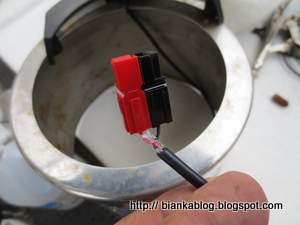
I mentioned in a previous post about using my Morningstar solar controller as a junction point for some new rewiring rather than the main breaker panel. I also added a  Rigrunner 4005 junction box. This box allows for several individually fused  Anderson Power Pole connectors to be plugged into the box.


 You can see some of the items I chose to connect to the box in the photo below:

Wednesday, January 14, 2015

ANOTHER ELECTRICAL PROJECT UPGRADE PART ONE

I've had  a Morningstar PS-15 ProStar 15 Solar Charge Controller  on board for over ten years. It's operated without a single problem in all the time. Once installed it has some nice features and protections. One is to use it's 15 amp output terminals to power electronics on board without running wires back to the already crowded main breaker panel.


I originally used this output to feed a single cigarette lighter type socket by the boats companion way to power the ENGEL refrigeration system.

It worked well but, I have been wanting to wire up some other devices to the Morningstar's output. So last year I took a little time to make this happen. I bought a two terminal barrier strip and installed it on a nearby bulkhead. Rewired the cigarette lighter socket to it.


I also ran a wire (white wire) to a new distribution panel which I will show in an upcoming post.

Monday, August 04, 2014

A SMALL CONNECTOR PROJECT

When I added the 48 volt solar panels to the bimini project I needed a way to connect both the 12 volt panels and 48 volt panels to their appropriate battery banks. So I rigged up a temporary junction box using a barrier strip and a small plastic project box as a temporary install. Here is what I had and it has work pretty good over the years.

 Well several years later I'm getting around to an upgrade . I'm finally getting around to making a better way to connect the solar panels to the solar controllers using Anderson Powerpole connectors. Like the ones shown here:

The blue connector signifies that the voltage the wires are carrying is 48 volts and is used to charge my electric propulsion battery bank. Speaking of colors notice how the red color has faded from this wire:
Exposure over the years has caused it to almost become white in color. Another good reason to have color coded connectors like Powerpoles on the ends of the wires.

 The Anderson Powerpole connectors can also be mated as shown here:

 This assures the proper ground (black connector) travel with the positive voltage wire. This helps to eliminate confusion with different voltage systems. You can also buy an optional clip that locks the pairs of Powerpole connectors to add some extra security that they won't pull apart.

So after replacing the lug connectors with Powerpoles I also put a little dab of Marine Goop on the back of each connector to help seal the wire and connectors.


Now both the 48 volt  and 12 volt solar panel connections can be easily accessed for troubleshooting and testing. I have plans to put some instrumentation in line to measure how well the panels are doing in the near future and I will post about those tests here on the blog.

Saturday, October 05, 2013

CODE BLUE FOR ELECTRIC PROPULSION

When I added the solar panels to help charge my 48 volt electric propulsion battery bank I used a Morningstar ProStar Charge Controller- PS-15M-48PG to regulate the solar panels charging. That controller also has a 48 volt 15 amp tap that provides a protected voltage out. It was very convenient to have that tap inside the boats cabin. I used it to power the 48 volt  to 12 volt converter which usually powers my laptop on board:

You can see the tap in the above picture. Even though the output is limited to 15 amps I am using  a75 amp Anderson Power Pole connectors. Why? Because that was what I had available at the time and it fit the input wires to the 48 volt to 12 volt converter. The problem is the red color of the positive wire looks the same as the 12 volt connector color code. Someone could accidentally plug in a 12 volt device if they are not familiar with the controller. This year I finally got around to correcting that. The Anderson color code for their connectors says blue should be used for 48 volts. So I ordered a Anderson Power Products 1300 connector, power pole, 75 amp, housing  that matches the Anderson standard. Nice thing about Anderson Power Poles it is relatively easy to change the connector case:


 So now one can immediately see that the 48 volt controller requires equipment connected to the 48 volt output requires a matching blue connector:

A small change like this can avoid confusion and accidental failures when one is using various voltages on a boat with electric propulsion. You can also see I used a P-Touch label on the controller to also let others know the voltage of the controller.

Sunday, August 04, 2013

UNDER THE BINNACLE:Wiring Update!

I needed to remove the old shift cable for the old diesel engine. I left it in place when I converted to electric propulsion because I thought I might use it to control some type of electronic switch down the road. But, after six years I realized I probably would never use it. So it was time for it to go. I also had other projects planned to mount on the binnacle and the shift lever would just be getting in the way.

 To get access for it's removal I had to remove the compass from the binnacle:

When I did I broke one of the wire connections to the LED light on the compass housing which provides illumination of the compass at night:

Not a big deal and easy enough to repair. But, then I thought this would be a good time to upgrade the connectors to Anderson Powerpoles .  So that's what I did. First the wires supplying power the binnacle:


Then added matching connectors to the wires that led to the LED compass light:


The Powerpole connectors will make it easier to disconnect things in the future and also offer a little more insulation and protection from shorts than the original spade lug connections.


Saturday, July 13, 2013

REWIRING THE HEAD LIGHT: PART TWO


Now that I had rewired the house wiring that connected to the light fixture with Anderson Powerpole connectors. It was time to rewire the fixture it's self. I soldered some wires to the connections for the switch and put Anderson Powerpole connectors on the other end of theses wires. I also soldered some wires onto the LED light being careful not to use too much heat while doing so to avoid any damage to the electronics of the light disk. NOTE: The LED light I used is not polarity sensitive so it did not matter which lead I made positive or negative. You need to check the wiring specs of the specific LED you may use as this is not always the case. 
At the other end of these wires I put on the appropriate colored Anderson Powerpole connectors.
Once all the connectors were on the proper wires. I used cables ties to make things secure, reinstalled the fixture into the head area and connected it to the house wiring:


I put some white electrical tape behind the LED just to make sure it would not short out to the light frame. Using the Anderson Powerpole connectors will allow for the easy addition of more LED lights or changes and modifications in the future. For example one thing I might add in the future is a red LED light for nightlight use and to prevent loss of night vision when sailing at night. Only thing remaining is to put the cover back on the fixture frame and this project is done for now:


Saturday, June 15, 2013

SOLAR BIMINI REWIRE

I installed the completed solar bimini on BIANKA back in 2010 though I did not finish posting about it until 2012. At the time I did a quick job of connecting the 48 volt Kanaka panels to the  Morningstar ProStar PS-15M-48V Charge Controller using the connectors that came with the panels to get the system up and running. In this case it was using  spade lugs connected to a two screw barrier strip and then down to the controller. I taped the whole thing in some electrical tape. This worked fine for awhile and it was always my intention to make things a little neater and more weatherproof at some point. Well, that project got moved up on the list this spring when I saw this:


I found that one of the solar panel connections had corroded and broken away from the spade lug.  


Indeed all the connections showed severe corrosion issues. Definitely time to replace this "temporary" setup. So that's what I did. I've mentioned before I really like Anderson Powerpole Connectors   for a lot of connections on board for a number of reason. One is they have wiping contacts that help clean the contact surface when connecting and disconnecting. Plus they are compact and can be ganged together. Another advantage is they have color coded cases available:

Since I'll be connecting 48 volt solar panels it is a good idea to follow the Anderson color code for their Power Poles. For 48 volts the recommended color is blue. I used it above for the positive 48 volt panel connection. This helps avoid confusion with the 12 volt panels that are also part of BIANKA's solar bimini.
Another thing with Anderson Powerpoles it is also easy to make up "two fer" cable harnesses so that in this case I can connect two separate solar panels to the same solar charge controller. This ability to quickly connect and disconnect the connectors helps in troubleshooting or taking voltage and current measurements of the panels.

As is the Anderson Power Poles are not particularly waterproof. So what I usually do is fill the back end of the connectors (where the wire enters) with Marine GOOP and then cover that with some electrical tape. Another wrap of electrical tape around the connector case joint ensures even more protection from moisture.    
With the new connections more waterproof than my previous installation I should not have to revisit this area of my electric propulsion charging system for long time.


Sunday, April 14, 2013

TROUBLE DOWN BELOW: Bilge Pump Switch

I mentioned that after the two plus feet of snow that the blizzard NEMO dumped on the Isle of Long I found BIANKA's bilge half filled with water when I finally was able to check on the boat. Since I could empty the water by activating the bilge pump with the manual switch it was apparent the automatic bilge switch was the problem:

Because of some freelance work commitments I was not able to replace the switch for several weeks. I emptied the bilge and hoped for the best. When I finally got back to the boat yesterday I was glad to find only about an a half inch of water in the bilge. It seems the blowing snow of the blizzard had found some ways into the boat where normal rains do not.  The bilge switch that failed was a Rule Super Switch that had worked reliably since I bought BIANKA in 1995 and may have been installed when the boat was commissioned in 1986. So it had a pretty long life in the Marine environment. When I remove the switch I was surprised to find there were two parts that made up the bilge switch. There was the float switch it's self and an optional guard case that it fit into:


Since I never had to mess with it in seventeen years it came as a surprise. The case helps keep debris away from the floating switch and also has a button you can push to test the switch to make sure it is working. This helps to make sure any debris will not cause the switch to stick in either on or off position.

In my researching for a new bilge pump switch I read several reviews the the newer bilge pump switches were a little more trouble prone. As they changed from a mercury switch to a metal ball conducting between to contacts. Some reviews mention the switches not lasting too long before failures. So I look at other choices and settled on  a Water Witch 101 control.


The Water Witch is an electronic switch the senses water between two electrodes to turn the bilge pump on. It was also considerably smaller than the Rule switch it was replacing:


The install was pretty simple and the manufacturers web site had a diagram on how to wire it up for my particular installation. I have a switch panel on board where I can manually power the bilge pump via a switch or switch it over and have a bilge switch automatically turn the bilge pump on once the water rises.
I used  Anderson Powerpole Connectors to connect the switch and bilge pump. This will allow for easier trouble shooting and/or replacement in the future.


I waterproofed the connectors with some   Marine Adhesive Goop and will further waterproof it later with some heat shrink and additional sealant in the near future. With the units wired up I tested it by putting the switch into a plastic cup and then added some water:


The pump operated as expected after a short delay to prevent cycling of the pump the bilge pump turned on. I then removed the switch from the water:

Again after a short delay it turned off. Convinced that the switch was working correctly I installed it into the bilge by attaching the switch unit to the bilge pump hose with a cable ty:


Well that's one pre launch project finished now on to the next one.

Saturday, March 30, 2013

INSTRUMENTATION PART 10: CURRENT METER INSTALLATION

With the battery voltage meter part of the instrumentation project finished. It was time to move on to the important current meter part of the project. BIANKA already had a Xantrex XBM battery monitor but, to see it required that I move away from the helm and lift a cockpit hatch and bend down to see it. It was awkward and inconvenient to look at while underway.


I went looking for another meter that could measure the current being drawn from or charging the battery bank. But, the catch was I did not want to have to put in another shunt for measuring  current in the battery circuit like the XBM battery monitor already used. I wanted to keep any extra connections to a minimum. To do that I needed to use a hall effect type of current meter.  It determines a current value by measuring the magnetic flux around a piece of wire with current flowing through it. I found exactly what I needed with a company called Devicecraft. They had a hall effect current meter with a transducer that would fit the 2 AWG wires that connect to  BIANKA's 48 volt electric propulsion battery bank.


The hook up is farely simple.


The display required a supply voltage and three wires that go to the hall effect transducer.  I needed to run the transducer wires about eight feet and used some   Twisted Servo Hookup Wire,   normally used in things like model cars and planes:


Like I did for some of the wires for the battery voltage meters part of this project I enclosed the transducer wires in a  Techflex General Purpose 1/4-inch Braided Cable Sleeve.  This was to keep the wires together and also protect them from chafing.

The 100 amp Hall effect sensor will fit over the 2 AWG cable that is used in the my electric propulsion system but, would not fit over the existing lug. So I needed cut the existing battery cable. I used a ratcheting wire cutter like a Klein ratcheting cable cutter which cuts heavy duty battery cable easily:

and makes a nice flush cut:


I took the opportunity to trim some other 2 AWG  battery interconnections that were a little too long from my initial electric propulsion installation five years ago too.  The Hall Effect transducer has a polarity in terms of it's display. That is if you a drawing current from the battery the display should show a negative sign in the display. Likewise when charging the battery it is useful to see the current flow as positive (no minus sign) on the digital display.  In order to make sure I got the polarity right I used some of the trimmed battery cables and a jumper to check the polarity of the meter.


Once I had established the proper orientation for the sensor I put it on the battery cable and crimped a new lug on the end and reconnected it to the battery. I then ran the sensor wires up through the cockpit wire conduit I made and into the helm area using one of the  Fiberglass Wire Pull Rods    I carry on board:

It was then just a matter of hooking up the sensor and power wires to the current display and the instrumentation project was finished:

I mounted it the box temporarily at the helm and used it on my fall cruise up the Hudson River and back. I still need to make a permanent platform for the box at the helm location but, that is a project for another day.