I mentioned that after the two plus feet of snow that the blizzard NEMO dumped on the Isle of Long I found BIANKA's bilge half filled with water when I finally was able to check on the boat. Since I could empty the water by activating the bilge pump with the manual switch it was apparent the automatic bilge switch was the problem:

Because of some freelance work commitments I was not able to replace the switch for several weeks. I emptied the bilge and hoped for the best. When I finally got back to the boat yesterday I was glad to find only about an a half inch of water in the bilge. It seems the blowing snow of the blizzard had found some ways into the boat where normal rains do not. The bilge switch that failed was a Rule Super Switch that had worked reliably since I bought BIANKA in 1995 and may have been installed when the boat was commissioned in 1986. So it had a pretty long life in the Marine environment. When I remove the switch I was surprised to find there were two parts that made up the bilge switch. There was the float switch it's self and an optional guard case that it fit into:

Since I never had to mess with it in seventeen years it came as a surprise. The case helps keep debris away from the floating switch and also has a button you can push to test the switch to make sure it is working. This helps to make sure any debris will not cause the switch to stick in either on or off position.
In my researching for a new bilge pump switch I read several reviews the the newer bilge pump switches were a little more trouble prone. As they changed from a mercury switch to a metal ball conducting between to contacts. Some reviews mention the switches not lasting too long before failures. So I look at other choices and settled on a
Water Witch 101 control.
The Water Witch is an electronic switch the senses water between two electrodes to turn the bilge pump on. It was also considerably smaller than the Rule switch it was replacing:
The install was pretty simple and the manufacturers web site had a diagram on how to wire it up for my particular installation. I have a switch panel on board where I can manually power the bilge pump via a switch or switch it over and have a bilge switch automatically turn the bilge pump on once the water rises.
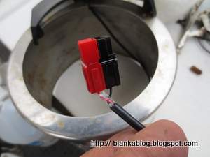
I used
Anderson Powerpole Connectors 
to connect the switch and bilge pump. This will allow for easier trouble shooting and/or replacement in the future.
I waterproofed the connectors with some
Marine Adhesive Goop
and will further waterproof it later with some heat shrink and additional sealant in the near future. With the units wired up I tested it by putting the switch into a plastic cup and then added some water:
The pump operated as expected after a short delay to prevent cycling of the pump the bilge pump turned on. I then removed the switch from the water:
Again after a short delay it turned off. Convinced that the switch was working correctly I installed it into the bilge by attaching the switch unit to the bilge pump hose with a cable ty:
Well that's one pre launch project finished now on to the next one.


 As this would allow the panel to be disconnected easily for repair or storage as needed. I've started to use them elsewhere on board with good results. They are quality connectors with wiping contacts that hold up very well in my experience. I already had several 4PDT Heavy Duty Toggle Switches on board that I was originally was going to use for the solar bimini. But, after finding some 48 volt solar panels I no longer needed to use the switches for charging.


.jpg)
.jpg)


