
The transmission was finally removed from the engine. I had spent most of the morning on the transmission but, things were about to move along. It was now time to do the big lift of the engine. In happier times I referred to the Westerbeke 27 as the "iron jenny" when it reliably started and allowed the boat to motor when the wind dropped. But, after a year of looking at it, dealing with mechanics scratching their heads at $75.00 per hour and more. I know refer to it now as the "iron pig" as it continued eat dollars from my wallet and prevented me from leaving the mooring all season.
So there it sat for over twenty years in the same place. With it's business end wide open like a mouth just daring me to come near. One slip up and I might have a crushed hand or 424 pounds of engine crashing down on the hull. In the back of my mind I'm thinking if there is an accident and I get my hand or arm caught between the hull and the engine would anybody be able to hear my crys for help. NOTE : Keep the cell phone handy.
The first thing to do was remove all the nuts to the bolts that held the motor mounts to the engine stringers. I had had conflicting information on how the bolts on the brackets that the engines mounts were sitting on were made. So I would need to find this out. I also removed the nuts and bolts that went through the side of the engine stringers that held the "L" brackets in place. Once this was done it was time to to lift the engine. I first took the two 18 inch pieces of chain and wrap them around the two arms sticking out from the engine and where the motor mounts attached. These chains were then attached to the hoist. As shown in the photo below:

Below is another shot showing both points of the lift.
 I now lifted this end of the engine enough so I could then see how the angle brackets and bolts would come off of the engine stringers. They actually turned out be nothing but two bolts screwed or spot welded into the metal brackets and they just lifted off the stringers. There was however a hole cut into the stringers to accommodate the head of the bolts that would have prevented the bracket from just sliding forward. If I had attempted to just slide the engine forward I would have done a lot of damage to the stringers. One of the "L" brackets is shown in the photo below:
  With new confidence that I could lift the engine by myself. It was now time to turn to the other end of the engine and do the same there. But, I would not be able to duplicate what I had just done in the confined space of the engine compartment. It would require a different approach.
NEXT: LIFTING THE OTHER END

-1.JPG)
-1.JPG)
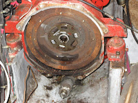
 If you look closely at the prop shaft in comparison with the previous pictures you will notice the prop shaft has also been cut down by about 9 inches. In the above photo you can see that the shaft face is flush while the previous photo shows the original shaft with the key way groove. The next step is to mount the motor.


.jpg)
.jpg)


