Showing posts with label engine. Show all posts
Showing posts with label engine. Show all posts
Saturday, April 11, 2015
SOME SPRING STEAM CLEANING
Having a boat with electric propulsion has some added benefits thanks to some of the on board power systems I use. One is the Honda 2000i generator which I use for battery charging at anchor and also when electro-sailing when the wind dies. The second is the 10 kilowatt AGM battery bank it's self. Thanks to the AMES 48 volt 1500 watt sine wave inverter I can tap into it and use 120 volt tools and devices like the Zojirushi bread maker. Though some of these are not necessary it enhances the cruising experience and helps maintain the boat. Another item I recently added on board is a DBTech Multi-Purpose Pressurized Steam Cleaner . Again not a necessary item but, it helps clean and sterilizes with it's steam. Often a lot easier than with other methods. I've used a steam cleaner on board before a few years ago when I started the process of converting BIANKA's now unused fuel tank into wash down water tank. Back then I used the heavily advertise Scunci Steam cleaner. It work well in cleaning the grime from the decades of use in the old fuel tank. I also used it at home. But, unfortunately it did not last. Rather than buy a new one I decided to see if the cheaper steam cleaner from DB Tech would do the job and save a few bucks in the process. So far it has. First let's look at what comes with the DB Tech steam cleaner:
Saturday, October 06, 2012
HONDA 2000i GENERATOR REPAIR: Pull Cord Replacement
Tweet
I've mention that my Honda 2000i generator has been very reliable for the past five years. So reliable that when it came time to repair it there was a lot of aggravation involved. The original problem was an expected one. The pull cord that allows one to start the engine broke. A simple problem that will probably befall all generators at some point if they are used often enough. What I did not expect was how seized up the outside screws that hold the 2000i covers on would be.

The aggravation was in how long it would take to remove them. In addition some of the screws were ...
I've mention that my Honda 2000i generator has been very reliable for the past five years. So reliable that when it came time to repair it there was a lot of aggravation involved. The original problem was an expected one. The pull cord that allows one to start the engine broke. A simple problem that will probably befall all generators at some point if they are used often enough. What I did not expect was how seized up the outside screws that hold the 2000i covers on would be.
The aggravation was in how long it would take to remove them. In addition some of the screws were ...
Thursday, October 14, 2010
REPORT FROM THE ANNAPOLIS BOAT SHOW:PART 4: ELECTRIFYING
I first went back to the Annapolis Boat Show back in 2007. At the time I was looking around for a replacement for the dead Westerbeke 27 diesel on board BIANKA. I was also debating between repowering with a new diesel or going electric. I was leaning toward a new BETA MARINE diesel. But, was hoping to find out about the going with electric propulsion. Sadly, there was only one electric system at the 2007 show that I found and it was expensive and made for a much larger boat than my 30 foot Nonsuch. But, happily in 2010 I found several booths where they were selling electric propulsion systems:

I spent a good part of the afternoon at the Annapolis Hybrid Marine booth. Who are the new U.S. distributors for the system I have on board which is an ASMO MARINE Thoosa 9000.

They had a very nice display that showed an actual entire system working:

There was a lot of interest from the crowd. I chimed in from time to time extolling the virtues of electric propulsion from my experience of having it on board BIANKA for the past three years. I also got to meet some readers of this blog which was fun too.
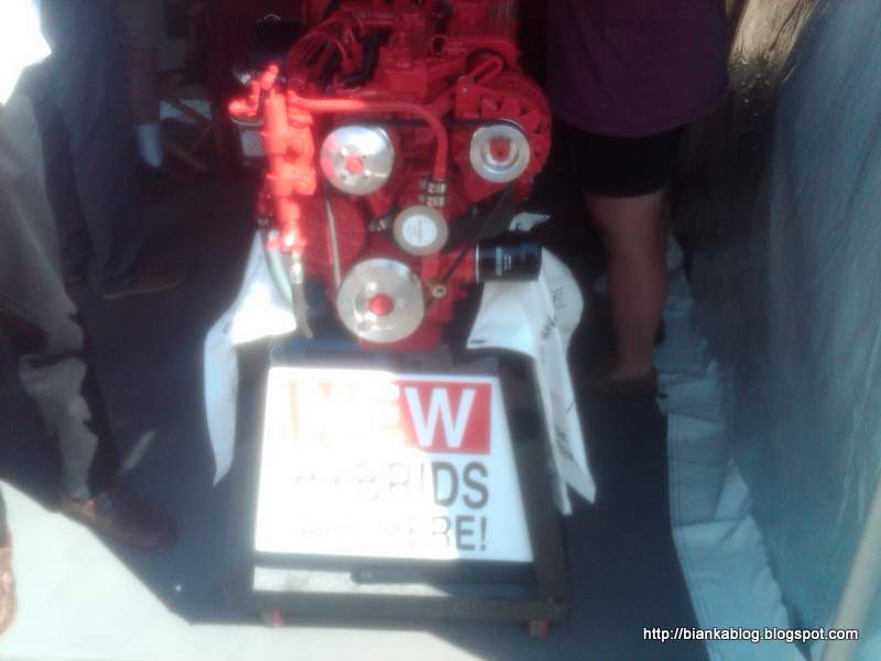
And for those who just can't live without the smell of diesel in the morning. BETA MARINE had an interesting Hybrid system that consisted of a Beta Marine diesel engine which had a Lynch electric motor attached.


I was glad to see BETA had chosen the same Lynch motor that is used on Thoosa 9000 on BIANKA.
 More expensive of course than a diesel alone. Plus you had the weight of both a diesel engine and batteries on board. Made for those who like the idea of electric propulsion but, don't want to make the leap to a pure electric system. But, for me I have gotten use to the smell of clean on board BIANKA to ever go back to having a diesel on board. My electric propulsion system provides everything I need in terms of propulsion without the mess of having a diesel on board. But, at least there are more choices out there.

I spent a good part of the afternoon at the Annapolis Hybrid Marine booth. Who are the new U.S. distributors for the system I have on board which is an ASMO MARINE Thoosa 9000.

They had a very nice display that showed an actual entire system working:

There was a lot of interest from the crowd. I chimed in from time to time extolling the virtues of electric propulsion from my experience of having it on board BIANKA for the past three years. I also got to meet some readers of this blog which was fun too.
And for those who just can't live without the smell of diesel in the morning. BETA MARINE had an interesting Hybrid system that consisted of a Beta Marine diesel engine which had a Lynch electric motor attached.
You could motor with electric or diesel. It would also regen when under sail. Lastly, you could disconnect the output shaft from the prop and use the engine as a generator by having the engine drive the Lynch electric motor as a generator directly to charge the batteries.


Saturday, January 26, 2008
How I began.

In order to remove the engine I decided to remove as many of the external parts as I could to make access and removal easier. In addition to the connected hoses and engine control linkages. The two major things I wanted to remove were the heat exchanger and the exhaust manifold.

This photo shows the engine with heat exchanger removed from the engine. The removal of the heat exchanger was first item to remove. It was not that difficult but, really is necessary in order to be able to access other areas of the engine to remove the exhaust manifold exchanger which was located under the rubber hose on the left side of the picture.
 This photo shows three of the four exhaust ports that the exhaust manifold attaches to. I was not able to see most of the nuts that had to be removed. Which is why you want a much access as possible which removing the heat exchanger allows.
 This is a before photo showing the exhaust manifold still attached to the engine. Note the overflow antifreeze tube which needs to be removed before removing the manifold.
 This is a photo after the exhaust manifold has been removed. Note the paper towels shoved into the top of the exhaust port elbows to keep dirt, parts, tools etc... from falling in.
NOTES:
Some things I have found so far that may be helpful to others who may have to work on their engines:
1) I purchased a set of ratcheting box end wrenches thinking they might help in removing the exhaust manifold and it's hard to reach location. They are useless for this task they are too big and do not fit. I have found the most useful tool to be a 1/4" Sears Craftsman metric ratchet kit. It is small enough to reach into the tight spaces needed.
2) I was able to reach six of the eight nuts holding the exhaust elbows to the aluminum exhaust manifold after first removing the heat exchanger creating space enough to reach my arm in and feel my way around to remove the nuts. The two remaining nuts I was able to reach easily from the other side of the engine. It went easier than I expected considering the difficult location.
Next step: Removing the transmission
The first lift of the engine
The first thing to do was remove all the nuts to the bolts that held the motor mounts to the engine stringers. I had had conflicting information on how the bolts on the brackets that the engines mounts were sitting on were made. So I would need to find this out. I also removed the nuts and bolts that went through the side of the engine stringers that held the "L" brackets in place. Once this was done it was time to to lift the engine. I first took the two 18 inch pieces of chain and wrap them around the two arms sticking out from the engine and where the motor mounts attached. These chains were then attached to the hoist. As shown in the photo below:

Below is another shot showing both points of the lift.
 I now lifted this end of the engine enough so I could then see how the angle brackets and bolts would come off of the engine stringers. They actually turned out be nothing but two bolts screwed or spot welded into the metal brackets and they just lifted off the stringers. There was however a hole cut into the stringers to accommodate the head of the bolts that would have prevented the bracket from just sliding forward. If I had attempted to just slide the engine forward I would have done a lot of damage to the stringers. One of the "L" brackets is shown in the photo below:
  With new confidence that I could lift the engine by myself. It was now time to turn to the other end of the engine and do the same there. But, I would not be able to duplicate what I had just done in the confined space of the engine compartment. It would require a different approach.
NEXT: LIFTING THE OTHER END
Thursday, December 07, 2006
Lessons learned: The raw water impeller.

Because of it's inaccessible location I decided to...
Subscribe to:
Posts (Atom)


.jpg)
.jpg)


