
Before beginning to remove the engine I will need to make room. The table needs to be removed and all the cushions removed in what could turn out to be a messy job in removing the engine.

Here is the Westerbeke 27 as it sits in what one mechanic called the tunnel. This is actually the rear of the engine which faces toward the bow of the boat. The V drive transmission is shown at the bottom of the photo. Not a lot of room to work in there so I will remove as much as I can before moving the engine.

This is the view from the other side of the engine. The front of the engine which faces aft in the Nonsuch.Where is the water pump? On the other side of the alternator and under the exhaust manifold. It was so much fun to change the impeller. Oh how I will miss doing that. What really bugs me though is before I decided to remove the engine I installed a
Speed Seal cover on the water pump and never did get to use it since I have decided to replace the engine.

In order to remove the engine I decided to remove as many of the external parts as I could to make access and removal easier. In addition to the connected hoses and engine control linkages. The two major things I wanted to remove were the heat exchanger and the exhaust manifold.

This photo shows the engine with heat exchanger removed from the engine. The removal of the heat exchanger was first item to remove. It was not that difficult but, really is necessary in order to be able to access other areas of the engine to remove the exhaust manifold exchanger which was located under the rubber hose on the left side of the picture.

This photo shows three of the four exhaust ports that the exhaust manifold attaches to. I was not able to see most of the nuts that had to be removed. Which is why you want a much access as possible which removing the heat exchanger allows.

This is a before photo showing the exhaust manifold still attached to the engine. Note the overflow antifreeze tube which needs to be removed before removing the manifold.

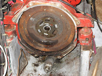
This is a photo after the exhaust manifold has been removed. Note the paper towels shoved into the top of the exhaust port elbows to keep dirt, parts, tools etc... from falling in.
NOTES:Some things I have found so far that may be helpful to others who may have to work on their engines:
1) I purchased a set of ratcheting box end wrenches thinking they might help in removing the exhaust manifold and it's hard to reach location. They are useless for this task they are too big and do not fit. I have found the most useful tool to be a 1/4" Sears Craftsman metric ratchet kit. It is small enough to reach into the tight spaces needed.
2) I was able to reach six of the eight nuts holding the exhaust elbows to the aluminum exhaust manifold after first removing the heat exchanger creating space enough to reach my arm in and feel my way around to remove the nuts. The two remaining nuts I was able to reach easily from the other side of the engine. It went easier than I expected considering the difficult location.
Next step: Removing the transmission
With the removal of the heat exchanger and exhaust manifold I was ready to remove the engine. Since I decided to replace the engine I was hoping to find a home for the old Westerbeke 27 it was a great engine had only 1900 hours on it and I thought sure someone with more mechanical skills than I could bring it back to life. Not to mention it would also provide a little down payment toward the cost of a new engine. What was the value of a non working diesel engine? One that I had already put in several hundred dollars in new parts. I had no idea. I had a few offers for various parts of the engine. But, I did not want to sell it piece meal. The Internet was not much help. While rowing out to the boat I engaged in a gam with a fellow sailor who suggest I get in touch with a mechanic in Connecticut he had dealt with. It sounded like a good idea!
I sent the mechanic an email asking if he knew anyone who might be interested in a non starting Westerbeke 27 engine. He asked for my phone number so he could make an offer. The offer was good but, I also added that he would have to help me remove the engine. He agreed. So things were looking up. I would sell the engine at a reasonable price and also have help in removing it. It was a win win situation, What could go wrong here.
Well plenty. As I made appointments with the mechanic to come help me remove the engine that he would then buy. He kept canceling and my boatyard was starting to get antsy to pull my boat. After several weeks of cancellations he finally called and said he would be by later in the day. Finally I would be able to get the engine out of the boat or so I thought.

The mechanic arrived on a 3:30 ferry. I thought this was strange that he would arrive so late. I had told him I would be available anytime from early in the morning. The boatyard workers leave around four or four thirty. So we would not be able to pull the engine off the boat today anyway and he would have to make another trip to pick it up. I thought coming this late would not make sense but, hey he is a mechanic and must have his reasons so I did not say anything. This was mistake one.
By the time we started to work on removing the engine it was after four in the afternoon. The first step was to remove the Hurth V drive transmission. It was held on to the engine by four bolts the top two bolts were removed quite easily. Unfortunately, the bottom two bolts were quite rusted due to twenty years of saltwater dripping down from zinc changes of the heat exchanger. These bolts are out of sight underneath the transmission and of course in a very difficult place to remove them.
The mechanic and I were able to get the one on the left in the photo out. but, the one on the right just would not budge no matter how much force we used. Heating up the area with a mapp gas torch did nothing but create a lot of smoke. Finally I had to get out my dremel tool and the bolt head was cut off. It was after about two hours of work that we were ready to remove the transmission. The only thing we had to do was slide the shaft back past the transmission lift off the transmission and then work on removing the engine. Should be simple right? Not in the world of marine engines. The shaft slid back only a few inches then stopped.

The photo above shows what the problem was. The boat was in the water and the shaft zinc was hitting the strut and preventing us from pushing the shaft back any further. This would have been a simple five minute fix if the mechanic had arrived earlier in the day and we could have had the boatyard put the boat on a lift, removed the zinc and continued to remove the engine. But, since it was seven o'clock at night the yard guys a had gone home and all work on the engine had to stop. Even the transmission had still not been removed. It gets worse.
The mechanic turns to me and says I need to get three hundred and fifty dollars from you. I say for what? Well, I really worked hard in trying to get this transmission off he says. But, I say part of the deal was you were supposed to help me remove the engine. He just shrugged. So much for deals. So work stops and I have laid out another three hundred and fifty dollars and the engine is still in the boat. Such is the life of a sailor.
NEXT: If you want something done....

As the saying goes if you want something done you have to do it yourself. Now that I have reached the mechanical cul de sac with the transmission removal I will do just that. I've had my fill of relying on mechanics. I spoke to the boatyard who now say they will be able remove the engine with their crane when the boat is in the yard. Before they wanted to do it when it was in the water because they said it was easier to move the boat around than the crane. I wish they would have told me this earlier. It was now late November and after they pull the boat they want to put other boats in front of mine so I am under a two day time limit to pull the engine. Can I do it? If I don't I will have to wait until next spring before they will be able to get the crane near enough to the boat to pull the engine. Meanwhile the iron pig waits on board....
So after a season of frustration, waiting, phone calls, dealing with mechanics and writing checks, it still came down to me having to remove the engine. I needed to get it done soon since the boatyard was pulling boats and filling up the yard. My boat would soon be surrounded by boats and they would not be able to get the crane close enough to pull the engine off the boat until next spring if I did not act soon. I sat down and tried to figure what I would need in the way of tools to move the 424 pound engine. I made one mistake in ordering but, it only cost me about thirty bucks. That was in thinking that an
engine leveler would be helpful in helping to move the Westerbeke 27 out from "the tunnel" under the cockpit. It turned out to be useless and unneeded. But, the two 18 inch chains that came with it were invaluable in moving the engine.
Well, maybe I made two ordering mistakes. The other mistake due to increasing age occurred in ordering
a 2 ton hoist from Northern Tool. I was looking at the catalog online and thinking with a 424 pound engine to lift that half ton hoist would be too close in in weight to be safe. My thinking was clouded as I was in my mind thinking that ton equals 1,000 pounds not 2,000 pounds. So in order to add an extra safety factor I ordered a 2 ton hoist! Doh! But, it did the job a little on the big side but, got the job done even if it was overkill.
In addition to the usual tools like metric socket wrenches and box end wrenches, a hand held 3lb mallet and various blocks and pieces of wood. I found the following tools also enabled me to remove the engine by myself.

The above photo shows basically what I used to lift the engine. The two 18" chains at the left came with the unneeded engine leveler. At the top of the photo is the 3" gas pipe was bought at Home Depot. I had two end caps put on to prevent the pipe from sliding over the lip the hatch when lifting the engine. It was added insurance besides making sure the pipe was secure. One should always make safety a top priority when doing this job. Finally, there is the two ton hoist. Big and hefty but, it did the job with ease and did not complain.
Some other indispensable tools I used:

CROWBARS! In addition to the two shown above. I also used an addition smaller one about a foot long that I keep on board and a small pry bar. I used everyone of them a some point in removing the engine. Sometimes I used two at once. They all came in very handy along with some long ago forgotten physics lessons regarding leverage.
NEXT: REMOVING THE TRANSMISSION.I had all my tools and a two day time limit to move the Westerbeke 27 engine into the cabin area to be removed by the yard crane. If I did not get it done in that time the engine would stay on board until late spring at the earliest. There was no time to waste but, I had absolutely no experience in doing this either. I got some helpful advice and encouragement from fellow Nonsuch owners at the International Nonsuch Association list serv. But, I would be on my own once on the boat. First I still needed to get the transmission off of the engine. So I set up my hoist system over the hatch as shown in the photo below:

Then I slid back the shaft that had been that had been the cause of the work stoppage in the
previous attempt to remove the transmission.

I tied some strong braided line around the transmission and attached it to hoist. I did this to help lift the transmission slightly and hold it suspended while I worked it of of the engine shaft. Removing the transmission was harder than I thought it would be. It did not slid off the engine shaft as easily as I thought it would. I guess after being mated to the engine for twenty years the shaft and transmission get pretty attached to one another. I had to pry and tap it off for about 45 minutes. All the time thinking that I might be doing something wrong because at first it hardly budged. But, finally it came loose after my gentle nudging. once the transmission was removed it was time to tackle the rest of the engine
NEXT: THE FIRST LIFT

The transmission was finally removed from the engine. I had spent most of the morning on the transmission but, things were about to move along. It was now time to do the big lift of the engine. In happier times I referred to the Westerbeke 27 as the "iron jenny" when it reliably started and allowed the boat to motor when the wind dropped. But, after a year of looking at it, dealing with mechanics scratching their heads at $75.00 per hour and more. I know refer to it now as the "iron pig" as it continued eat dollars from my wallet and prevented me from leaving the mooring all season.
So there it sat for over twenty years in the same place. With it's business end wide open like a mouth just daring me to come near. One slip up and I might have a crushed hand or 424 pounds of engine crashing down on the hull. In the back of my mind I'm thinking if there is an accident and I get my hand or arm caught between the hull and the engine would anybody be able to hear my crys for help. NOTE : Keep the cell phone handy.
The first thing to do was remove all the nuts to the bolts that held the motor mounts to the engine stringers. I had had conflicting information on how the bolts on the brackets that the engines mounts were sitting on were made. So I would need to find this out. I also removed the nuts and bolts that went through the side of the engine stringers that held the "L" brackets in place. Once this was done it was time to to lift the engine. I first took the two 18 inch pieces of chain and wrap them around the two arms sticking out from the engine and where the motor mounts attached. These chains were then attached to the hoist. As shown in the photo below:

Below is another shot showing both points of the lift.
 I now lifted this end of the engine enough so I could then see how the angle brackets and bolts would come off of the engine stringers. They actually turned out be nothing but two bolts screwed or spot welded into the metal brackets and they just lifted off the stringers. There was however a hole cut into the stringers to accommodate the head of the bolts that would have prevented the bracket from just sliding forward. If I had attempted to just slide the engine forward I would have done a lot of damage to the stringers. One of the "L" brackets is shown in the photo below:
  With new confidence that I could lift the engine by myself. It was now time to turn to the other end of the engine and do the same there. But, I would not be able to duplicate what I had just done in the confined space of the engine compartment. It would require a different approach.
NEXT: LIFTING THE OTHER END
So after feeling much more confident that I would be able to move this 424 lb hunk of metal around. It was time to tackle the other end of the engine. There was no room to rig a hoist so this would require a different technique. Problem one was to remove the engine off of the "L" brackets like I did in the other side of the engine. With the other side of the engine still attached to the hoist and lifted slightly off of the engine bed as shown in the photo below:

I would only have the other side of the engine resting on the engine bed. This is where the crowbars come in. By using scrap hardwood blocks I was able to lift one side of the engine enough to raise it above the projecting screws of the "L" bracket and remove the bracket off the stringers. Unfortuntely, I was only able to do this on one side. On the other side I was not able to remove the bolts that held the "L" bracket to the engine stringer because of it's location. But, the other three "L" were off. Again, the crowbars were the solution. Using two crowbars I was able to lift that side of the engine and carefully shift the engine forward a little until it cleared the still attached "L" bracket bolts and then lower the engine back onto the engine stringer. The photo below shows the motor mount just foward of the bracket after this proceedure"

Notice the rust on the "L" bracket on the stringer. That is from twenty years of salt water impeller changes and the water that leaked on it.
So now the engine is resting on the two aft engine brackets on the stringers and being held by the hoist and chains on the other end. I slowly used the crowbars to lift and slide the engine forward on the engine stringers until it stopped sliding easily. Time to go back into the cabin.
I slowly lowered the engine cabin side of the engine down via the hoist until the motor mounts rested on two sturdy wood blocks on each side of the engine. The engine was now far enough forward in the cabin that I could now reposition the chains and hoist onto the two lifting rings located on top of the Westerbeke engine. As shown below:

Once this was done it was simply a matter of lifting the engine and slowly pulling it into the cabin and setting it down on some blocks inside the cabin and then have the boatyard crane lift it out of the boat. . Here are some more photos of the process:


The above photo is and overhead shot looking down into the cabin after the engine has been moved forward into the main cabin. NOTE: The green sheet that the motor is resting on is a piece of Lexan plastic. It not only protects the cabin sole but also allows the engine to slide a little if you need to reposition it slightly.
The only thing left is to have the yard guys come with the crane and lift the engine out of the cabin.


 And so over a year after the engine stopped starting, two mechanics and hundreds of dollars later the once faithful Westerbeke 27 has finally made it back on land twenty one years after it last was there. It is bitter sweet to see it go as I think of all the places it has taken me and the BIANKA when the wind died. I'll be posting some of those journeys here in the future. But, now it is time to move and figure out what will replace it. I learned a lot about the diesel engine in the past year and that should prove valuable in the future. As this chapter of my experience with BIANKA ends there is a new one about to begin. But, first it's time for a vacation a get some sailing in to start to make up for this last years lost season.
-1.jpg) I sketched up some ideas on a napkin. I showed some of my ideas to some coworkers who are more mechanically inclined than I am. They were greeted with mixed results. So I decided I probably needed some professional help. While I have done some simple fiberglass repairs over the years. I was not about to learn fiber glassing and stringer fabrication 101 on my boat by myself. So I turned to a local fellow named Malcom who I had first contacted when I was considering replacing the Westerbeke diesel with a new Beta Marine engine as he was the local representative for Beta. But, he also refurbishes yachts of all sizes and does repairs. To me he was exactly the guy I wanted to help me with this part of the electrification project. So here is what he came up with:
I sketched up some ideas on a napkin. I showed some of my ideas to some coworkers who are more mechanically inclined than I am. They were greeted with mixed results. So I decided I probably needed some professional help. While I have done some simple fiberglass repairs over the years. I was not about to learn fiber glassing and stringer fabrication 101 on my boat by myself. So I turned to a local fellow named Malcom who I had first contacted when I was considering replacing the Westerbeke diesel with a new Beta Marine engine as he was the local representative for Beta. But, he also refurbishes yachts of all sizes and does repairs. To me he was exactly the guy I wanted to help me with this part of the electrification project. So here is what he came up with: The first step was to extend the existing stringers all the way to the edge of the cabin as shown above. The existing stringer edge was routered out and the new stringer additions were glued and screwed to them.
-1.JPG) Here's a shot from above showing both extension stringers installed. The next step was to rough up the area around the stringers to remove the paint and provide a surface that the epoxy would better adhere to when fiber glassing begins:
Here's a shot from above showing both extension stringers installed. The next step was to rough up the area around the stringers to remove the paint and provide a surface that the epoxy would better adhere to when fiber glassing begins: -1.JPG)
 The above photo shows another angle. Notice the bilge blower hose in middle of the picture. Here is a tip: As I mentioned in a previous post using the bilge blower came in handy to help remove the dust and particles created by grinding down the surface around the stringers. It will also help with the removing the fumes involved with the next step: Fiber glassing.
The above photo shows another angle. Notice the bilge blower hose in middle of the picture. Here is a tip: As I mentioned in a previous post using the bilge blower came in handy to help remove the dust and particles created by grinding down the surface around the stringers. It will also help with the removing the fumes involved with the next step: Fiber glassing.-1.JPG)
.jpg)
-1.JPG)
-1.JPG)
-1.JPG)
-1.JPG)

-1.JPG)
-1.JPG)
-1.JPG)
-1.JPG)

-1.JPG)
-1.JPG)
 If you look closely at the prop shaft in comparison with the previous pictures you will notice the prop shaft has also been cut down by about 9 inches. In the above photo you can see that the shaft face is flush while the previous photo shows the original shaft with the key way groove. The next step is to mount the motor.
-1.JPG)
 The advantage of placing the batteries in the location where the engine was is that the trim of the boat in the water should be about the same and also keep the wire runs as short as possible. Using cardboard cutouts of the same dimensions as the 8A4D AGM batteries I will be ordering I decided on the arrangement above. This seemed to be the best arrangement for maintenance and weight distribution and wire runs. The 8A4D batteries weigh 129 lbs each which after removing the 424 pound Westerbeke 27, starting battery, diesel fuel and associated components probably gives a slight weight advantage to the electric propulsion system. One of the reasons I choose to place the battery on the left side in the above photo is to provide the proper balance for weight distribution. Next to that battery is the now empty diesel fuel tank. So this battery will help provide the needed weight on the starboard side to balance out missing weight of the diesel fuel and keep the trim of the boat about the same.
The advantage of placing the batteries in the location where the engine was is that the trim of the boat in the water should be about the same and also keep the wire runs as short as possible. Using cardboard cutouts of the same dimensions as the 8A4D AGM batteries I will be ordering I decided on the arrangement above. This seemed to be the best arrangement for maintenance and weight distribution and wire runs. The 8A4D batteries weigh 129 lbs each which after removing the 424 pound Westerbeke 27, starting battery, diesel fuel and associated components probably gives a slight weight advantage to the electric propulsion system. One of the reasons I choose to place the battery on the left side in the above photo is to provide the proper balance for weight distribution. Next to that battery is the now empty diesel fuel tank. So this battery will help provide the needed weight on the starboard side to balance out missing weight of the diesel fuel and keep the trim of the boat about the same.-1.JPG)


.jpg)
.jpg)


