Showing posts with label rewiring. Show all posts

Wednesday, January 14, 2015

ANOTHER ELECTRICAL PROJECT UPGRADE PART ONE

I've had  a Morningstar PS-15 ProStar 15 Solar Charge Controller  on board for over ten years. It's operated without a single problem in all the time. Once installed it has some nice features and protections. One is to use it's 15 amp output terminals to power electronics on board without running wires back to the already crowded main breaker panel.


I originally used this output to feed a single cigarette lighter type socket by the boats companion way to power the ENGEL refrigeration system.

It worked well but, I have been wanting to wire up some other devices to the Morningstar's output. So last year I took a little time to make this happen. I bought a two terminal barrier strip and installed it on a nearby bulkhead. Rewired the cigarette lighter socket to it.


I also ran a wire (white wire) to a new distribution panel which I will show in an upcoming post.

Saturday, October 05, 2013

CODE BLUE FOR ELECTRIC PROPULSION

When I added the solar panels to help charge my 48 volt electric propulsion battery bank I used a Morningstar ProStar Charge Controller- PS-15M-48PG to regulate the solar panels charging. That controller also has a 48 volt 15 amp tap that provides a protected voltage out. It was very convenient to have that tap inside the boats cabin. I used it to power the 48 volt  to 12 volt converter which usually powers my laptop on board:

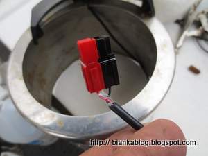
You can see the tap in the above picture. Even though the output is limited to 15 amps I am using  a75 amp Anderson Power Pole connectors. Why? Because that was what I had available at the time and it fit the input wires to the 48 volt to 12 volt converter. The problem is the red color of the positive wire looks the same as the 12 volt connector color code. Someone could accidentally plug in a 12 volt device if they are not familiar with the controller. This year I finally got around to correcting that. The Anderson color code for their connectors says blue should be used for 48 volts. So I ordered a Anderson Power Products 1300 connector, power pole, 75 amp, housing  that matches the Anderson standard. Nice thing about Anderson Power Poles it is relatively easy to change the connector case:


 So now one can immediately see that the 48 volt controller requires equipment connected to the 48 volt output requires a matching blue connector:

A small change like this can avoid confusion and accidental failures when one is using various voltages on a boat with electric propulsion. You can also see I used a P-Touch label on the controller to also let others know the voltage of the controller.

Sunday, August 04, 2013

UNDER THE BINNACLE:Wiring Update!

I needed to remove the old shift cable for the old diesel engine. I left it in place when I converted to electric propulsion because I thought I might use it to control some type of electronic switch down the road. But, after six years I realized I probably would never use it. So it was time for it to go. I also had other projects planned to mount on the binnacle and the shift lever would just be getting in the way.

 To get access for it's removal I had to remove the compass from the binnacle:

When I did I broke one of the wire connections to the LED light on the compass housing which provides illumination of the compass at night:

Not a big deal and easy enough to repair. But, then I thought this would be a good time to upgrade the connectors to Anderson Powerpoles .  So that's what I did. First the wires supplying power the binnacle:


Then added matching connectors to the wires that led to the LED compass light:


The Powerpole connectors will make it easier to disconnect things in the future and also offer a little more insulation and protection from shorts than the original spade lug connections.


Saturday, July 13, 2013

REWIRING THE HEAD LIGHT: PART TWO


Now that I had rewired the house wiring that connected to the light fixture with Anderson Powerpole connectors. It was time to rewire the fixture it's self. I soldered some wires to the connections for the switch and put Anderson Powerpole connectors on the other end of theses wires. I also soldered some wires onto the LED light being careful not to use too much heat while doing so to avoid any damage to the electronics of the light disk. NOTE: The LED light I used is not polarity sensitive so it did not matter which lead I made positive or negative. You need to check the wiring specs of the specific LED you may use as this is not always the case. 
At the other end of these wires I put on the appropriate colored Anderson Powerpole connectors.
Once all the connectors were on the proper wires. I used cables ties to make things secure, reinstalled the fixture into the head area and connected it to the house wiring:


I put some white electrical tape behind the LED just to make sure it would not short out to the light frame. Using the Anderson Powerpole connectors will allow for the easy addition of more LED lights or changes and modifications in the future. For example one thing I might add in the future is a red LED light for nightlight use and to prevent loss of night vision when sailing at night. Only thing remaining is to put the cover back on the fixture frame and this project is done for now:


Wednesday, July 10, 2013

REWIRING THE HEAD LIGHT: PART ONE


When I bought BIANKA she had a combination of lights. Some were fluorescent and some were regular tungsten lamps. Which are power hogs compared to the florescent lights. I've been replacing the tungsten lamps with much more energy efficient LED lamps. I also am replacing the fluorescent fixtures with LEDs as they fail instead of getting them rebuilt. The fluorescent fixture in the head area died a while ago and the other day I decided to rewire it for an LED replacement:


After making sure the breaker was turned off I first removed the bulbs and then the metal shield that covered the ballast electronics::

I was then able to cut the power wires to the fixture and remove the four screws holding the fixture to the cabin top. There were two wood shim pieces on the back of the light to take in account the curvature of the cabin top. I am going to reuse the fluorescent fixture and it's switch but, I have no use for the failed ballast circuit board so I will remove it and a lot of the associated wiring:


To remove the ballast board I had to drill out the two rivets holding the circuit board to the light frame from the back of the fixture:
With the circuit board gone there is a lot more room to install the LED replacement lamp(s):
Turning back to the light wiring. I noticed that someone had used wire nuts to attach the light to the boat wiring:

This is not a good idea for a whole bunch of reason on board a boat, Especially from a corrosion standpoint. I removed the wire nuts and replaced them with versatile  Anderson Powerpole Connectors :
This will make it east to reconnect the new LED lights when the fixture is installed. It will also allow for easier modification and changes in the future.